
Cylindrical Vacuum Chamber Option

It is an option for each cylindrical vacuum chambers.
NW flange
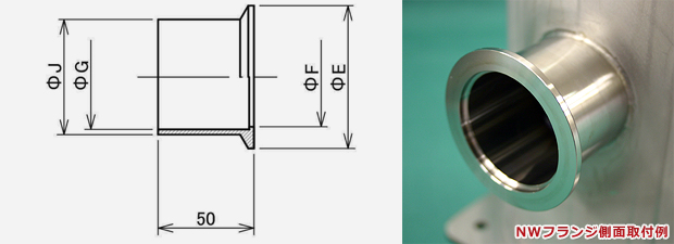
NW flange size table
| Nominal diameter | NW10 | NW16 | NW25 | NW40 | NW50 |
|---|---|---|---|---|---|
| ΦE | 30 | 30 | 40 | 55 | 75 |
| ΦF | 12.2 | 17.2 | 26.2 | 41.1 | 52.2 |
| ΦG | 10 | 16 | 24 | 39 | 55 |
| ΦJ | 13.8 | 21.7 | 27.2 | 42.7 | 60.5 |
socket
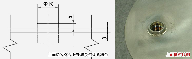
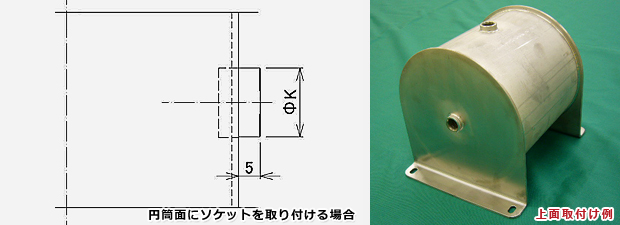
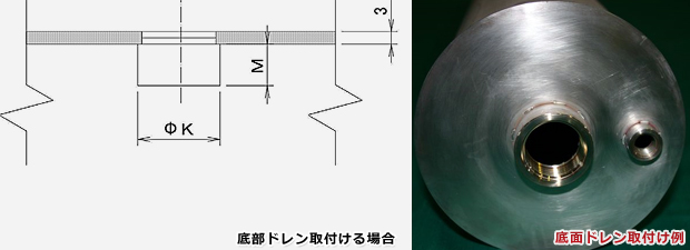
Socket connection
| Nominal diameter | ΦK | M |
|---|---|---|
| Rc1/8 | 13.9 | 30 |
| Rc1/4 | 17.1 | 13 |
| Rc3/8 | 21.1 | 14 |
| Rc1/2 | 25 | 18 |
| Rc3/4 | 31 | 19 |
| Rc1 | 37.9 | 24 |
Gauge port
Gauge port mounting details
When installing the gauge port on the pipe cylindrical surface
Gauge port connection
| Model | GP-15 | GP-18 | GP-21 | GP-28 |
|---|---|---|---|---|
| A | 16 | 40 | 25 | (55) |
| B | 19 | 40 | 28 | (55) |
| C | 22 | 36 | 28 | (55) |
| L | 28.8 | 55 | 40 | (40) |
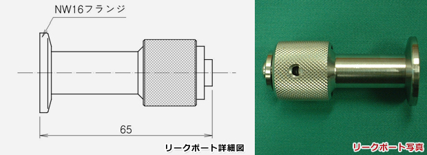
Leak port
Peep window
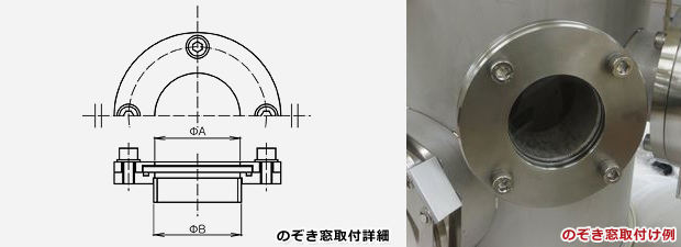
Peep window size chart
| Specified dimensions(ΦA) | B | Fuselage pipe diameter |
|---|---|---|
| 32.5 | 34 | All applicable |
| 47.1 | 38.6 | All applicable |
| 74.3 | 76.3 | Φ139.8Φ216.3Φ318.5 |
| 112.3 | 114.3 | Φ216.3Φ318.5 |
VG ・ VF flange details
VGFlange
| Model number | Outer diameter Size |
A | ΦD | T | S | Φa | ΦC | N | h | GⅠ | GⅡ | H |
|---|---|---|---|---|---|---|---|---|---|---|---|---|
| VG20-20A | 27.2 | 28.0 | 80 | 8 | 4 | 25 | 60 | 4 | 10 | 34 | 44 | 3.0 |
| VG25-25A | 34.0 | 35.0 | 90 | 8 | 4 | 32 | 70 | 4 | 10 | 40 | 50 | 3.0 |
| VG40-40A | 48.6 | 49.5 | 105 | 10 | 5 | 46 | 85 | 4 | 10 | 55 | 65 | 3.0 |
| VG50-50A | 60.5 | 61.0 | 120 | 10 | 5 | 57 | 100 | 4 | 10 | 70 | 80 | 3.0 |
| VG65-65A | 76.3 | 77.0 | 145 | 10 | 5 | 73 | 120 | 4 | 12 | 85 | 95 | 3.0 |
| VG80-80A | 89.1 | 90.0 | 160 | 12 | 6 | 86 | 135 | 4 | 12 | 100 | 110 | 3.0 |
| VG100-100A | 114.3 | 115.0 | 185 | 12 | 6 | 111 | 160 | 8 | 12 | 120 | 130 | 3.0 |
VF flange
| Model number | Outer diameter Size |
A | ΦD | T | S | Φa | ΦC | N | h |
|---|---|---|---|---|---|---|---|---|---|
| VF20-20A | 27.2 | 28.0 | 80 | 8 | 4 | 25 | 60 | 4 | 10 |
| VF25-25A | 34.0 | 35.0 | 90 | 8 | 4 | 32 | 70 | 4 | 10 |
| VF40-40A | 48.6 | 49.5 | 105 | 10 | 5 | 46 | 85 | 4 | 10 |
| VF50-50A | 60.5 | 61.0 | 120 | 10 | 5 | 57 | 100 | 4 | 10 |
| VF65-65A | 76.3 | 77.0 | 145 | 10 | 5 | 73 | 120 | 4 | 12 |
| VF80-80A | 89.1 | 90.0 | 160 | 12 | 6 | 86 | 135 | 4 | 12 |
| VF100-100A | 114.3 | 115.0 | 185 | 12 | 6 | 111 | 160 | 8 | 12 |